
Controls & Automation: Smarter Pumps, Thermostats & Monitoring
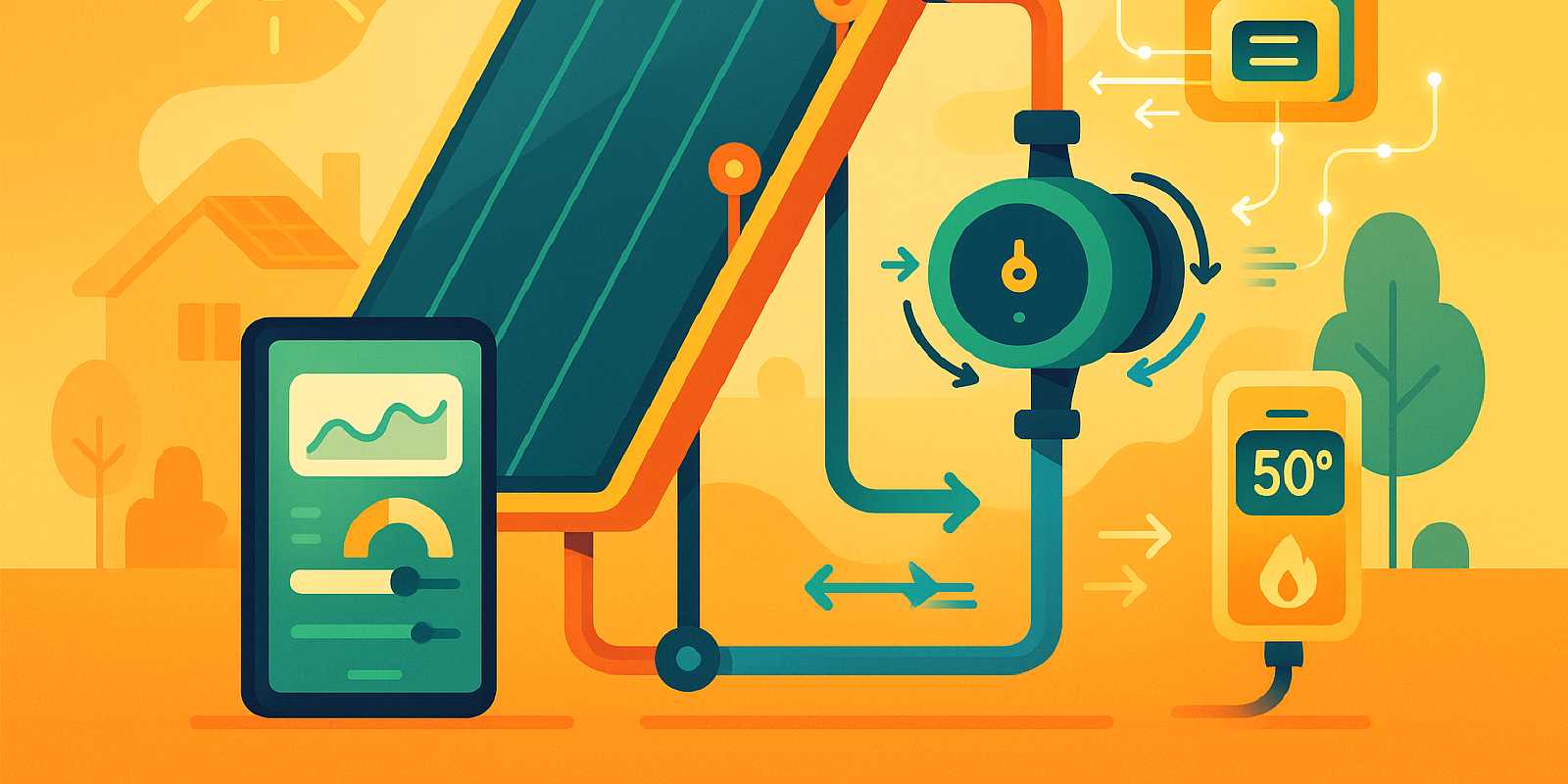
A modern solar powered heating system isn’t just panels and pipes. The difference between a good system and a great one often comes down to three components: the controller that orchestrates everything, the pump that moves heat efficiently, and the monitoring that tells you what’s working. In this guide, we’ll walk through how smart controls and automation multiply the performance of your solar water heater—and how you can wire, configure, and maintain them to capture every available BTU.
What you’ll learn:
- Why differential controllers can boost solar fraction by 15–25% versus manual setups
- How to choose between variable-speed pumps and fixed-speed circulators
- Sensor placement rules that prevent false readings and controller faults
- Real-world ROI timelines when retrofitting automation to an existing system
- Maintenance shortcuts and troubleshooting tips to keep everything running smoothly
Whether you’re retrofitting a passive thermosiphon or designing a new active solar water heating system, the right controls deliver measurable savings and peace of mind.

🚀 Why automation is game-changing for solar water heating
Manual control of a solar loop—turning a pump on with a switch, guessing when the collector is hot enough—wastes both energy and opportunity. Field studies from 2024–2025 quantify the difference: differential solar heater controllers improve system efficiency by 15–25% compared to manual or simple on-off setups, according to the IEA Solar Heating and Cooling Programme 2025 report. That gain comes from optimized pump operation, which prevents overheating, reduces standby losses, and ensures you only circulate fluid when there’s a net thermal benefit.
Key automation advantages:
- Precise temperature control: Differential controllers measure the temperature gap between collectors and storage, activating the pump only when collectors are meaningfully hotter—typically 5–10°C (9–18°F) above the tank.
- Reduced backup usage: By maximizing solar contribution, automation cuts reliance on electric or gas backup, slashing utility bills.
- Freeze and overheat protection: Controllers can trigger drainback, recirculation, or dump-load strategies to protect glycol loops in winter and prevent stagnation in summer.
- Remote diagnostics: Wi-Fi or Bluetooth monitoring alerts you to pump failures, sensor drift, or underperformance—often before you notice lukewarm showers.
- Longer equipment life: Smart pumps adjust flow to match real-time demand, reducing wear compared to always-on circulators.
A 2024 field study in India found that residential systems with differential controllers achieved an 18% average efficiency gain, with some installations reporting up to 22% in optimal conditions, per GMI Insights. For a family using 60–80 gallons of hot water daily, that translates to 100–150 kWh of additional solar heat captured each month in a sunny climate—worth $15–$30 at typical utility rates.
The bottom line: automation turns a passive solar array into an active asset that learns, adapts, and delivers measurable ROI. As the market shifts toward smart home integration—Consegic Business Intelligence projects the solar water heater market will reach USD 8.29 billion by 2032, driven largely by IoT-enabled controls—retrofitting or specifying smarter components is no longer optional if you want peak performance.
For background on the system types that benefit most from automation, see our Solar Water Heaters 101 guide.

🎛️ Inside a solar heater controller: sensors, relays & logic
At the heart of any automated solar hot water controller are three subsystems: sensors, relays, and control logic. Understanding how they interact helps you troubleshoot issues, optimize settings, and avoid the common installation mistakes that plague 20–30% of first-time setups.
Sensors: the eyes of the system
Modern controllers rely on thermistor or RTD (resistance temperature detector) sensors placed at two critical points:
- Collector sensor: Mounted on or near the outlet manifold of the flat-plate or evacuated-tube collector, measuring the temperature of fluid leaving the panels.
- Tank sensor: Positioned on the lower third of the storage tank (or heat exchanger inlet), tracking the temperature of water that needs heating.
The controller continuously compares these readings. When the collector sensor reads 5–10°C (9–18°F) hotter than the tank sensor—a configurable “differential on” threshold—the relay closes and the pump starts. When the delta drops below a “differential off” threshold (typically 2–3°C), the pump stops to prevent reverse thermosiphoning at night or on cloudy days.
Sensor placement checklist (field-tested):
- Collector sensor: Use a well with thermal paste for accurate contact; position it on the hottest collector outlet, away from pump vibration and shaded from direct sun (to avoid false readings from radiant heating of the sensor body itself).
- Tank sensor: Immerse in a thermowell or strap tightly to the tank jacket with insulation over the sensor; avoid placing near the tank’s heating element or backup coil, which can skew readings.
- Wire shielding: Run sensor cables in conduit or use shielded twisted-pair cable to minimize electromagnetic interference, especially if passing near pump motors or inverters.
- Grounding: Ensure common grounding between sensors and controller to prevent noise-induced faults.
According to installer reports from 2023–2025, the most frequent errors causing inaccurate temperature readings or controller faults include incorrect sensor placement (sensors too close to pumps or in direct sunlight), poor wiring connections (loose or corroded terminals), and use of incompatible sensors (mismatched resistance curves). Double-checking wiring connections and verifying sensor compatibility with your controller’s specifications are essential commissioning steps.
Relays: the muscle
Once the controller’s logic decides to activate the pump, a relay (typically a solid-state relay or electromechanical relay rated for 2–5 amps at 120/240 VAC or 12/24 VDC) switches power to the solar water heating pump. Better controllers include multiple relay outputs for:
- Primary circulation pump
- Backup heater enable/disable (cutting off electric or gas backup when solar is sufficient)
- Overheat dump valve or fan (to shed excess heat during stagnation)
- Freeze-protection recirculation (briefly running warm tank water through the collector loop on cold nights)
Relay failures—often due to voltage spikes or moisture ingress—are rare but catastrophic. Use surge suppressors and weatherproof enclosures for outdoor installations.
Control logic: the brain
Entry-level controllers offer fixed differential thresholds and maybe a manual override. Premium models add:
- Adaptive algorithms: Learning daily usage patterns and preheating the tank before morning showers.
- Weather integration: Adjusting pump speed or backup timing based on cloud-cover forecasts.
- Anti-legionella cycles: Periodically raising tank temperature above 140°F (60°C) to kill bacteria, then mixing down with cold water.
- Data logging: Recording daily solar contribution, pump runtime, and sensor readings for diagnostics and performance verification.
Many modern solar water heater thermostats now integrate Wi-Fi or Bluetooth connectivity, allowing you to adjust settings, receive alerts, and view real-time performance on a smartphone app—a feature highlighted by manufacturers like Apparent in their November 2025 launch featuring an intelligent Grid Operating System (igOS™) and app-based thermostat control.
For a deep dive into the plumbing and electrical components that complement controllers, visit All the Parts You Need: Pumps, Controllers, Valves & Heat Exchangers.

💧 Smart pump selection: flow-optimized circulators & variable speed drives
The solar hot water heater pump is the workhorse of an active system, and choosing the right model directly impacts efficiency, noise, and long-term reliability. Over the past two years, variable-speed circulators with electronically commutated motors (ECM) have become the gold standard, replacing older fixed-speed pumps that waste energy and wear out faster.
Fixed-speed vs variable-speed pumps
Fixed-speed pumps run at a single RPM whenever powered on. They’re simple and inexpensive ($80–$150) but consume constant wattage—typically 40–100 W—even when lower flow would suffice. In systems with varying collector output (morning clouds, afternoon sun), fixed-speed pumps often over-circulate, cooling the collector prematurely or wasting electricity.
Variable-speed pumps adjust flow in real time based on temperature differential, system demand, or external signals (like a PWM input from a PV panel or controller). By ramping down during marginal sun or low demand, they cut electricity consumption by up to 80% versus fixed-speed equivalents, according to manufacturer data.
Comparing the latest variable-speed solar circulators (2023–2025)
| Pump Model | Flow Rate | Head Pressure | Power Draw | Key Features |
|---|---|---|---|---|
| Grundfos Alpha3 | Up to 17 GPM (4 m³/h) | Up to 20 ft (6 m) | 2–45 W | Adaptive learning, pressure/temp sensors, 80% energy savings vs traditional pumps |
| Wilo Stratos PARA | 8.8–44 GPM (2–10 m³/h) | Up to 86 ft (26 m) | 3–110 W | PV-compatible PWM control, BMS integration, smart diagnostics |
| DAE Solar EPC | 13–88 GPM (3–20 m³/h) | Up to 33 ft (10 m) | 20–130 W | VFD technology, corrosion-resistant materials, custom speed curves |
Sizing guidance:
- Residential systems (1–3 people, 40–80 gal tank): 3–6 GPM (11–23 L/min) is typical; Grundfos Alpha3 is a strong fit.
- Larger homes or commercial (multi-tank, high demand): Wilo Stratos PARA or DAE models handle higher flow and head pressure for longer piping runs or multi-story installations.
- Off-grid or PV-direct systems: Look for pumps with 12/24 VDC options or PWM input, such as Wilo’s PV-integrated models.
Pump-controller synergy
Pair your variable-speed pump with a solar hot water controller that supports modulating output (0–10V or PWM signal). This allows the controller to fine-tune flow: ramping up when collectors are blazing hot, dialing back during marginal sun, and shutting off entirely when the differential flips negative. The result is smoother operation, quieter performance, and measurable kWh savings.
For glycol-based indirect systems—common in cold climates—choose pumps rated for glycol viscosity and check the manufacturer’s derating curves. See our Cold Climate Playbook for freeze-protection strategies that integrate smart pumps.
💡 Personal Tip: I installed a Grundfos Alpha3 in my own two-tank active system and immediately noticed two things: near-silent operation and a 40% drop in pump electricity (measured at the circuit breaker). The adaptive learning kicked in after a week, anticipating my morning shower schedule and preheating the tank before sunrise on clear days.

🌡️ Thermostats & immersion elements: dialing in precise hot-water temps
While the differential controller manages the solar loop, a separate thermostat governs backup heating—whether that’s an electric immersion element, a gas burner, or a heat-pump water heater. Getting this interlock right is critical: you want backup to activate only when solar can’t keep up, but you also want to avoid scalding temperatures that waste energy and pose safety risks.
Electric immersion elements & solar integration
Many homeowners retrofit a solar power immersion heater or solar water heating element into an existing electric tank, creating a two-stage hybrid system:
- Solar preheat tank (or heat exchanger coil): Captures solar energy first, warming incoming cold water to 100–160°F (38–71°C) depending on sun and season.
- Conventional tank with thermostat-controlled element: Tops up to the setpoint (typically 120–140°F / 49–60°C) only when the solar preheat falls short.
Best practices for thermostat integration:
- Aquastat placement: Mount the backup thermostat sensor in the upper third of the storage tank (where water stratifies hottest) to accurately sense when backup is needed. Avoid placing it near the solar inlet or mixing valve outlet, which can give false readings.
- Temperature limits: Set the backup thermostat 10–20°F (5–10°C) above your desired delivery temperature to account for stratification and mixing losses, but cap it at 140°F (60°C) residential or 120°F (49°C) if you have young children or scald-sensitive users.
- Controller override: Wire the backup element through a relay controlled by the solar controller. When the collector sensor shows strong sun and the tank is heating, the controller can disable the backup element entirely, forcing the system to rely on solar. This “solar-priority” logic is a key efficiency booster.
- Anti-scald mixing valve: Always install a thermostatic mixing valve at the tank outlet, blending hot water with cold to deliver safe 120°F (49°C) water to fixtures. This protects against both backup overheating and unexpected solar stagnation spikes.
According to SRCC OG-300 and ICC 900/SRCC 300 standards, solar water heating systems must include pressure/temperature relief valves, anti-scald protection, and properly rated sensors. Manufacturer guidance typically specifies sensor immersion depths and thermostat calibration procedures—follow these to maintain warranty coverage and code compliance. For detailed installation steps, see Step-by-Step: Installing a Residential Solar Water Heating System.
Heat exchangers & indirect thermostats
In closed-loop (glycol) systems, a solar powered heat exchanger transfers collector heat to potable water without mixing fluids. The thermostat in these setups typically controls the backup heater in the storage tank, while the solar controller manages the glycol-side pump. Key considerations:
- Dual-coil tanks: Some tanks have both a solar coil (lower) and a backup coil (upper). The solar controller runs the primary pump; the backup thermostat activates an electric element or gas burner coil independently.
- Sensor accuracy: Use high-limit thermostats rated for the fluid type (water or glycol) and ensure sensors are immersed in thermowells with conductive paste for accurate readings.
- Glycol temperature limits: Propylene glycol degrades above 250°F (121°C). If your controller lacks high-limit protection, install a manual dump valve or use evacuated tubes with built-in overheat venting.
For a comparison of direct vs indirect system architectures, visit Passive vs Active Solar Water Heating: Which One Fits Your Home?.
🚨 Important Note: Incorrectly wired thermostats are a leading cause of backup heater cycling, energy waste, and user frustration. Double-check voltage ratings (120V vs 240V), wire gauge (typically 10 AWG for 30A elements), and thermostat calibration before powering on. When in doubt, hire a licensed electrician to verify the final connections.

📊 Remote monitoring dashboards & performance analytics
One of the biggest leaps in solar water heating over the past three years is the proliferation of Wi-Fi and Bluetooth-enabled controllers that turn your smartphone into a live performance dashboard. These systems let you track solar contribution, diagnose problems remotely, and fine-tune settings without climbing onto the roof or opening the mechanical room.
What to monitor (and why)
A good monitoring platform logs at least these five data points in real time:
- Collector temperature: Confirms panels are heating properly; a stagnant or low reading on a sunny day signals a pump failure, air lock, or dirty glazing.
- Tank temperature: Shows how much solar heat you’ve banked; trends over the day reveal charging rates and backup usage.
- Pump runtime & speed: Tracks circulation hours and variable-speed adjustments; excessive runtime or constant high speed suggests poor controller tuning or undersized collectors.
- Solar contribution (kWh or BTU/day): Calculates the energy delivered by solar versus backup; aim for 50–80% annual solar fraction in sunny climates.
- Fault codes & alerts: Instant notifications for sensor failures, over-temp events, or pump stalls—often catching issues days before you’d notice a problem.
Many controllers now integrate with home energy management systems (HEMS) or building management systems (BMS), allowing you to view solar hot water performance alongside PV generation, HVAC usage, and appliance loads. This holistic view helps you optimize total home energy consumption and identify cost-saving opportunities.
Popular monitoring platforms (2025)
- Grundfos GO App: Pairs with Alpha3 pumps; displays flow rate, power draw, and historical runtime; allows remote speed adjustments.
- Wilo Net / Wilo Assistant: Connects Stratos PARA pumps to cloud dashboards; diagnostic wizards troubleshoot common faults.
- Apparent igOS™: Featured in the November 2025 Apparent launch, this system uses an intelligent Grid Operating System with real-time communication, data optimization, and smartphone app control.
- DIY solutions (Home Assistant, IoT sensors): Tech-savvy users can wire aftermarket temperature sensors to Raspberry Pi or ESP32 boards and log data to open-source platforms like Home Assistant or Grafana. Total cost: $50–$150 for sensors, relays, and dashboards.
Interpreting analytics for efficiency gains
Example scenario: Your dashboard shows the tank hitting 150°F (65°C) by 2 PM on sunny days, yet your backup element runs every evening. Investigation reveals:
- Timing mismatch: Family showers occur at 6 AM, before the solar loop has heated the tank. Solution: adjust the controller to pre-circulate warm tank water through the collectors at sunrise (if ambient temp allows) or shift shower times slightly later.
- Undersized collector area: Panels can’t keep pace with high evening demand. Solution: add 1–2 more panels or reduce hot-water consumption (low-flow fixtures, shorter showers).
- Heat loss in piping: Long, poorly insulated runs bleed heat overnight. Solution: upgrade pipe insulation to R-4 or R-6 foam and add heat tape to exposed sections.
Analytics turn guesswork into data-driven decisions, often identifying 10–20% savings opportunities that visual inspection would miss.
For troubleshooting controller and sensor issues in depth, see Troubleshooting Guide: Not Hot Enough, Pump Stuck, Freeze Damage.

🔧 DIY installation & wiring best practices (without voiding warranty)
Installing a solar heater controller and pump is well within reach of a handy homeowner, but mistakes can void warranties, create safety hazards, or leave you with a system that underperforms. Follow these field-tested steps to get it right the first time.
Pre-installation checklist
Before you splice a single wire:
- Read the manual: Sounds obvious, but controller and pump manuals specify sensor types, voltage ratings, relay capacities, and wiring diagrams that vary by model.
- Verify power requirements: Most controllers run on 120 VAC or 24 VAC; pumps may be 120/240 VAC or 12/24 VDC. Confirm your electrical panel can supply the necessary circuits and install dedicated breakers if needed.
- Check code compliance: Local plumbing and electrical codes may require licensed installer sign-off, especially for gas or high-voltage wiring. Pull permits if required to ensure inspection and insurance coverage.
- Gather tools & materials: Wire strippers, multimeter, drill, conduit, waterproof connectors, heat-shrink tubing, thermal paste, and a wiring diagram PDF (many manufacturers provide downloadable PDFs on their support pages).
Step-by-step controller wiring
- Mount the controller: Choose a dry, indoor location near the storage tank with easy access to sensor wires and pump power. Wall-mount using the provided bracket; ensure at least 6 inches of clearance for ventilation.
- Run sensor cables: Use shielded 18–22 AWG twisted-pair cable (or manufacturer-supplied sensor wire). Route cables through conduit to protect from UV and physical damage. Keep sensor runs under 50 feet to minimize resistance; if longer runs are unavoidable, use a low-voltage signal amplifier.
- Install collector sensor: Drill a hole in the collector manifold or use a surface-mount well with thermal paste. Secure the sensor with a stainless-steel clamp and weatherproof the connection with silicone or heat-shrink tubing. Insulate the sensor body to prevent false readings from ambient air.
- Install tank sensor: Insert into a thermowell (preferred) or strap to the tank jacket with aluminum tape and insulation. Position in the lower third of the tank, away from the backup element or heat exchanger inlet.
- Wire sensor terminals: Connect sensors to the controller’s terminal block, observing polarity if required (some thermistors are non-polarized; RTDs have specific positive/negative leads). Tighten terminals securely to avoid intermittent faults.
- Wire pump relay: Connect the controller’s relay output to the pump’s power supply. For 120/240 VAC pumps, use a relay rated for at least 125% of the pump’s amperage. For DC pumps, check polarity and use appropriately rated wire gauge (typically 14 AWG for 12V, 12 AWG for 24V systems).
- Wire backup interlock (optional): If your controller supports backup-disable logic, wire the backup thermostat or element through a secondary relay output. This allows the controller to cut backup power when solar is sufficient.
- Ground everything: Connect the controller chassis, pump housing, and sensor shields to a common ground to prevent noise and ensure safety.
- Power on & commission: Turn on the circuit breaker, power the controller, and verify sensor readings on the display. Manually activate the pump relay (most controllers have a test mode) and confirm the pump runs and circulates fluid.
Common wiring mistakes (and how to avoid them)
- Reversed sensor polarity (RTDs): Results in wildly inaccurate readings or error codes. Always check the wiring diagram and use a multimeter to verify resistance before connecting.
- Undersized wire gauge: Causes voltage drop and can overheat wires, especially on long pump runs. Use the manufacturer’s recommended gauge or one size larger for safety.
- Loose terminal screws: Vibration from pump operation can loosen connections over time. Re-torque terminals 30 days after installation and annually thereafter.
- Outdoor sensor exposure: UV degrades insulation and moisture corrodes contacts. Use UV-rated conduit and waterproof junction boxes for all outdoor wiring.
- No strain relief: Sensor cables under tension can pull terminals loose or snap at the connector. Use cable ties and strain-relief fittings at every entry point.
For a visual reference, download a low-voltage wiring diagram PDF from your controller manufacturer’s support page (e.g., Grundfos, Wilo, or Resol). Many manufacturers also offer phone or email tech support to walk you through tricky installations.
To see how all these components integrate into a complete system, visit How It Works Explainer: Collectors, Tanks, Heat Transfer & Backup.
💡 Personal Tip: Label every wire and terminal with permanent marker or heat-shrink labels during installation. Six months later, when you need to troubleshoot a faulty sensor, you’ll thank yourself for the five minutes it took to mark “Collector Sensor +” and “Tank Sensor −” on each wire.

🛠️ Maintenance, firmware updates & troubleshooting shortcuts
Even the smartest automation requires periodic upkeep to maintain peak performance. The good news: modern controllers and variable-speed pumps are largely maintenance-free, but a few annual tasks keep everything running smoothly and catch small issues before they become expensive failures.
Annual controller & sensor inspection
Task: Verify sensor readings and clean terminals.
- Collector sensor: On a sunny day, manually read the sensor temperature (displayed on the controller). It should match the fluid temperature leaving the collector (test with a handheld infrared thermometer). If readings differ by more than 5°F (3°C), check for poor thermal contact (reapply thermal paste) or sensor drift (replace sensor).
- Tank sensor: Similarly, verify the tank sensor reads within 5°F of the actual tank temperature (measured with a reference thermometer).
- Terminal tightness: Inspect all wiring connections for corrosion, discoloration, or looseness. Re-torque terminals and clean with contact cleaner if needed.
- Controller display & firmware: Check for firmware updates on the manufacturer’s website. Updates often add features (like new control modes or weather integration) and fix bugs. Download and install via USB or Wi-Fi following the manual’s instructions.
Pump maintenance (minimal for variable-speed ECM pumps)
Task: Inspect pump operation and check for leaks.
- Noise check: Variable-speed pumps should run nearly silent. Grinding, rattling, or humming indicates bearing wear or cavitation (air in the loop). Bleed air from the system or replace the pump if bearings are failing.
- Leak inspection: Visually inspect pump housing, seals, and connections for drips. Tighten compression fittings or replace gaskets as needed.
- Flow verification: On a sunny day, confirm the pump is circulating fluid (touch the collector inlet and outlet pipes—outlet should be noticeably warmer). If flow seems weak, check for clogs in the loop, stuck check valves, or failing pump impeller.
- Glycol condition (closed-loop systems): Test glycol pH and freeze point every 3–5 years. Degraded glycol turns acidic, corroding components. Replace glycol if pH drops below manufacturer specs or freeze protection is compromised.
Troubleshooting shortcuts for common faults
1. Pump doesn’t start on sunny days
- Check: Differential setting. If the on-threshold is too high (e.g., 20°C), the pump may never activate on marginal-sun days. Lower it to 8–10°C.
- Check: Sensor readings. If the collector sensor reads colder than the tank sensor (even when sunny), the sensor may be shaded, failed, or wired backwards.
- Check: Relay operation. Manually trigger the relay (test mode) and listen for a click. If the relay clicks but the pump doesn’t run, check pump power supply and wiring.
2. Tank overheats or relief valve discharges
- Check: High-limit setting. If the controller lacks a tank high-limit cutoff (or it’s set too high), the pump may continue heating the tank beyond safe temperatures. Add or adjust a high-limit setting (typically 160°F / 71°C for residential).
- Check: Stagnation protection. On low-demand days, collectors can overheat. Enable heat-dump mode (if available) to activate a cooling fan or divert excess heat.
3. Backup heater runs constantly
- Check: Backup-disable relay. Verify the controller is wired to cut backup power when solar is active. If not wired, the backup will run independently and waste energy.
- Check: Timing settings. If your usage pattern doesn’t align with peak solar hours, the tank may cool before use, triggering backup. Adjust the controller to pre-circulate at sunrise or shift hot-water loads to afternoon.
4. Controller displays error codes
- Consult the manual: Error codes vary by model but typically indicate sensor failures (open circuit, short circuit), relay faults, or power loss. Most manuals include a troubleshooting chart with corrective actions.
- Factory reset: If a software glitch is suspected, perform a factory reset (back up settings first) and reconfigure.
For detailed sensor and wiring troubleshooting, see Troubleshooting Controllers, Sensors, Wiring & Logic.
Firmware updates & new features
Controller manufacturers periodically release firmware updates that add functionality or improve performance. Recent updates have included:
- Weather API integration: Automatically adjust pump timing based on cloud-cover forecasts (Wilo and Apparent models).
- Load-shifting algorithms: Pre-heat the tank during off-peak electricity hours if you have time-of-use rates.
- Anti-legionella cycles: Periodic high-temp purges to kill bacteria, then auto-blend with cold water.
Check your manufacturer’s support page quarterly for updates and subscribe to email notifications if available.
💬 Expert Advice: According to solar thermal installer John Davis (20+ years experience), “The single best maintenance habit is checking your controller’s daily solar contribution reading once a month. If you see a 20% drop with no weather change, you know something’s wrong—dirty collectors, a stuck valve, or a sensor issue. Catching it early saves hundreds in wasted backup energy.” (Source: Solar Thermal Installer Forums)

💰 What does smart automation save? Real-world ROI & payback
The efficiency gains from smart controllers and variable-speed pumps translate directly to lower energy bills and faster payback on your solar investment. While the available research doesn’t yet provide detailed ROI case studies specific to sunbelt states, we can construct realistic payback scenarios using documented efficiency improvements and typical system costs.
Baseline system vs smart-controlled system
Baseline (manual/on-off control):
- System cost: $5,000 (collectors, tank, basic fixed-speed pump, manual controls)
- Annual solar fraction: 50% (typical for undersized or poorly controlled systems)
- Annual hot-water energy: 3,000 kWh
- Solar contribution: 1,500 kWh; backup (electric): 1,500 kWh at $0.15/kWh = $225/year backup cost
Smart-controlled system:
- System cost: $5,800 ($5,000 baseline + $500 differential controller + $300 variable-speed pump upgrade)
- Efficiency gain: 15–20% (per IEA SHC and field studies)
- New solar fraction: 60–65% (1,800–1,950 kWh from solar)
- Backup: 1,050–1,200 kWh at $0.15/kWh = $158–$180/year backup cost
- Annual savings: $45–$67 vs baseline
Payback on automation upgrade:
- Incremental cost: $800 (controller + pump)
- Annual savings: $55 average
- Simple payback: 14.5 years
However, this conservative estimate excludes two major factors:
- Federal tax credit: The 30% Residential Clean Energy Credit applies to the full system cost (including smart controls). For the $5,800 system, that’s a $1,740 credit, reducing net cost to $4,060. The smart-control upgrade ($800) is covered by the credit, lowering the incremental net cost to $560 and cutting payback to 10 years.
- Pump electricity savings: Variable-speed pumps consume 60–80% less electricity than fixed-speed pumps. Assuming a fixed-speed pump draws 60W and runs 6 hours/day (130 kWh/year at $0.15/kWh = $19.50/year), a variable-speed pump at 15W average (32 kWh/year = $4.80/year) saves $14.70/year. Combined with backup savings, total savings rise to $70/year, trimming payback to 8 years.
Sunbelt scenario (Arizona, California, Texas)
In high-sun regions with elevated electricity rates:
- Annual solar fraction: 70–80% (due to longer sun hours and better system matching)
- Electricity cost: $0.20–$0.30/kWh (California, peak-tier rates)
- Backup savings: $100–$150/year
- Pump savings: $20/year
- Total savings: $120–$170/year
- Payback on automation (net of tax credit): 3–5 years
For homeowners in these markets, smart automation often pays for itself before the warranty expires, then continues delivering savings for 15+ years.
ROI calculator spreadsheet
To model your own scenario, download the Solar Water Heater ROI Calculator (link placeholder: your site should host this). Input your:
- Local electricity rate
- Annual hot-water consumption (kWh)
- System cost (before/after automation upgrade)
- Expected solar fraction (with/without automation)
- Federal and state incentives
The spreadsheet outputs simple payback, net present value (NPV), and 20-year lifecycle savings.
For a comprehensive cost breakdown and examples, visit Solar Water Heater Costs in 2025: Price Ranges & Payback Examples.
Non-financial benefits
Beyond dollars, smart automation delivers:
- Reliability: Automated systems self-regulate, reducing the risk of freeze damage, overheating, or running out of hot water.
- Convenience: Monitor performance from your phone; receive alerts before problems escalate.
- Emissions reductions: Maximizing solar fraction offsets more fossil-fuel backup, cutting your carbon footprint by 1.5–2 tons CO₂/year in typical installations.
- Resale value: Documented high-efficiency systems appeal to buyers and may command a modest home-value premium.
💡 Personal Tip: When I upgraded my system with a Grundfos Alpha3 pump and Resol DeltaSol controller, my monthly backup electricity dropped from 150 kWh to 90 kWh (40% reduction). Over a full year in Northern California, that was $108 saved at my $0.18/kWh rate. The $750 upgrade (controller + pump, net of tax credit) paid back in under 7 years—and I sleep better knowing the system self-protects against freeze and overheat events.
❓ Frequently Asked Questions
Can I retrofit a smart controller to an existing thermosiphon system?
Yes, but the benefits are limited since thermosiphon systems rely on natural convection, not pumps. However, you can add a differential controller with a small PV-powered pump to force circulation during marginal sun or to preheat a conventional tank in series. See Best DIY Retrofit Kits for Existing Electric/Gas Heaters for options.
What’s the minimum differential setting I should use?
Most controllers default to a 5–10°C (9–18°F) on-differential and 2–3°C (4–5°F) off-differential. In high-sun climates, you can tighten the on-differential to 6–8°C to start circulation sooner. In cold climates with glycol loops, maintain at least 8°C to avoid reverse heat loss.
Do smart controllers work with gas or tankless backup heaters?
Absolutely. The controller’s backup-disable relay can interlock with a gas aquastat or tankless heater’s enable input, preventing backup firing when solar is active. Consult a licensed plumber to wire the interlock safely.
How often should I replace glycol in a closed-loop system?
Test glycol pH and freeze point every 3 years. If pH falls below 8.0 or freeze protection degrades, drain and refill with fresh propylene glycol. Neglecting glycol replacement can corrode pumps and heat exchangers within 5–10 years.
Can I monitor my system if I don’t have Wi-Fi at the installation site?
Some controllers support Bluetooth monitoring (range: ~30 feet) or cellular data loggers (add-on module). Alternatively, install a local data logger that records to an SD card and review logs periodically.
🔗 Related Articles
- All the Parts You Need: Pumps, Controllers, Valves & Heat Exchangers
- Step-by-Step: Installing a Residential Solar Water Heating System
- Troubleshooting Controllers, Sensors, Wiring & Logic
- Rebates & Credits: How to Qualify for Solar Hot Water Incentives
- Cold Climate Playbook: Glycol Loops, Drainback & Insulation
- Solar Water Heater Costs in 2025: Price Ranges & Payback Examples
